AutoGarden: First Steps

So, I have some plants outside that I take care of – tomatoes, peppers, etc. One day, I thought it would be nice if they took care of themselves more often. Besides being interesting simply because it’s cool, this project is also very useful in a practical way.

What did I name it? AutoGarden. Note: as far as I’m aware, not related to any transforming cars.

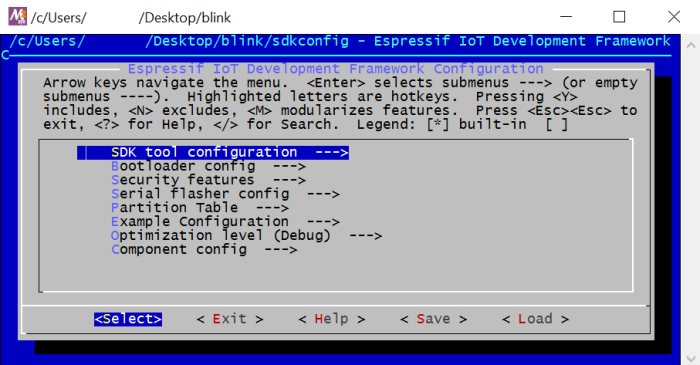
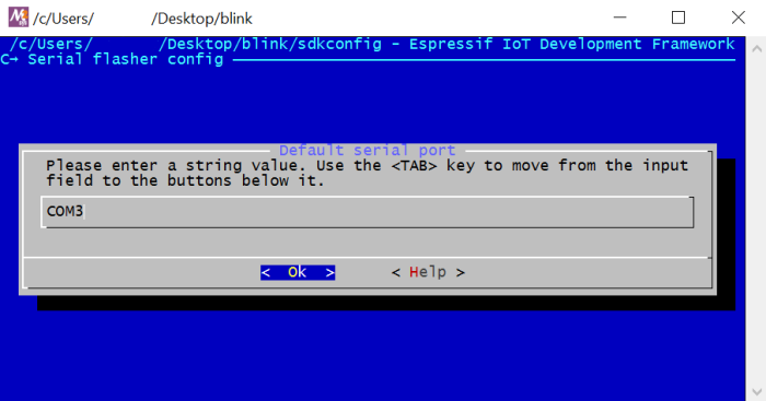
I’m using an Adafruit ESP8266 HUZZAH board with a soil moisture sensor and an Adafruit plastic solenoid water valve. The ESP8266 logs moisture data online; when I press a button on the same online dashboard, the ESP8266 should open the valve and water the plants. The dashboard I used at first was Thingspeak, but I’m going to switch to Cayenne because I like their system better.


This slideshow requires JavaScript.

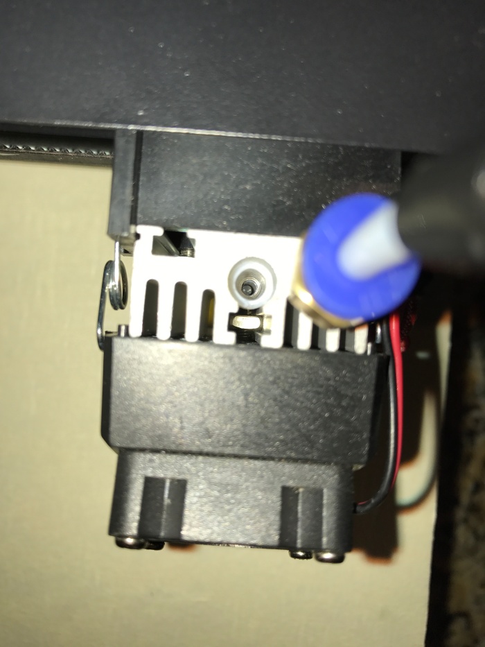
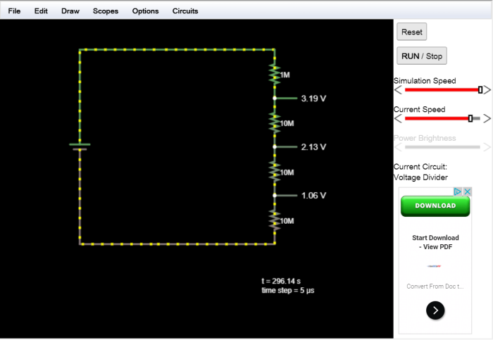
I’ll make a circuit diagram soon, but it’s a fairly simple configuration. The white wire is connecting pin 16 to the reset pin, which allows the ESP8266 to wake up from deep sleep. One orange wire is the ground wire that goes to the source of the MOSFET; the drain is connected to the solenoid negative, and the gate is the green wire, connected to pin 5. Lastly, other than the 220 ohm resistor (which is for the gate pin), all of the resistors on the red breadboard are part of a big voltage divider that scales the 0-3.3V analog signal from the moisture sensor down to a 0-1V signal, which is what this ESP8266 breakout can handle. The other orange wire connects the output of the divider to the analog pin (A).

circuit.png
Here’s a picture of the voltage divider circuit on http://falstad.com.

Now, the most important part: the power. I’m making this project be something that I can “forget” about – not that I ever would forget about a MCU running in my backyard and posting data online. However, if I did forget about it, I want it to be able to keep running forever (a very long time) on its own. So, I’m using a lot of deep sleep; the MCU wakes up, logs its data, checks for commands (i.e., water the soil), and then goes to sleep for hours on end. This should conserve a lot of energy.

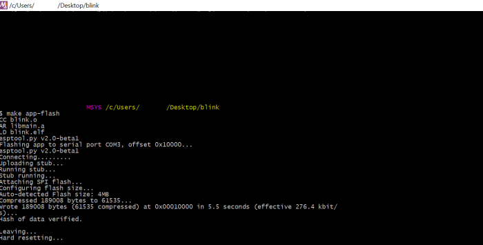
So, I set all of this up for a nice test. How did I power it? A couple of 9V batteries, one for the MCU and one for the valve. *scoff* Like that was going to work.

graph.png
Note that the graph starts at 100% – the soil was saturated with water.

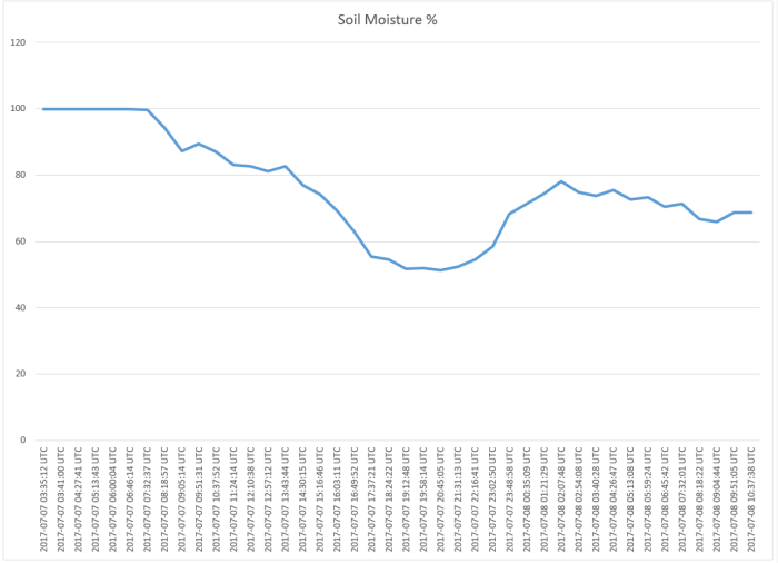
As you can probably tell, the 9V battery route isn’t the best strategy if I’m looking for longevity and forgettability1. It ran for around 31 hours.

So, this is great data to have, and I’m glad I did the trial run. Needless to say, I need more power.

I’m not inclined to use AC power because (a) that feels like cheating2 and (b) this project is designed to be in the elements, and I don’t want to have to waterproof 120 volts. So, I’m going to the next best thing – solar power!

I ordered a simple, cheap, 2.5 watt solar panel, an MPPT charger, a 1.3 Ah lead acid battery, and – of course – a bigger waterproof box. That will arrive soon and I’ll be able to put it together.

Another interesting issue was water – specifically, water going where it’s not supposed to be. I’m using a waterproof case with a cable gland, so the one thing there should not be inside the case is liquid water. But, behold, there was water.

IMG_1902

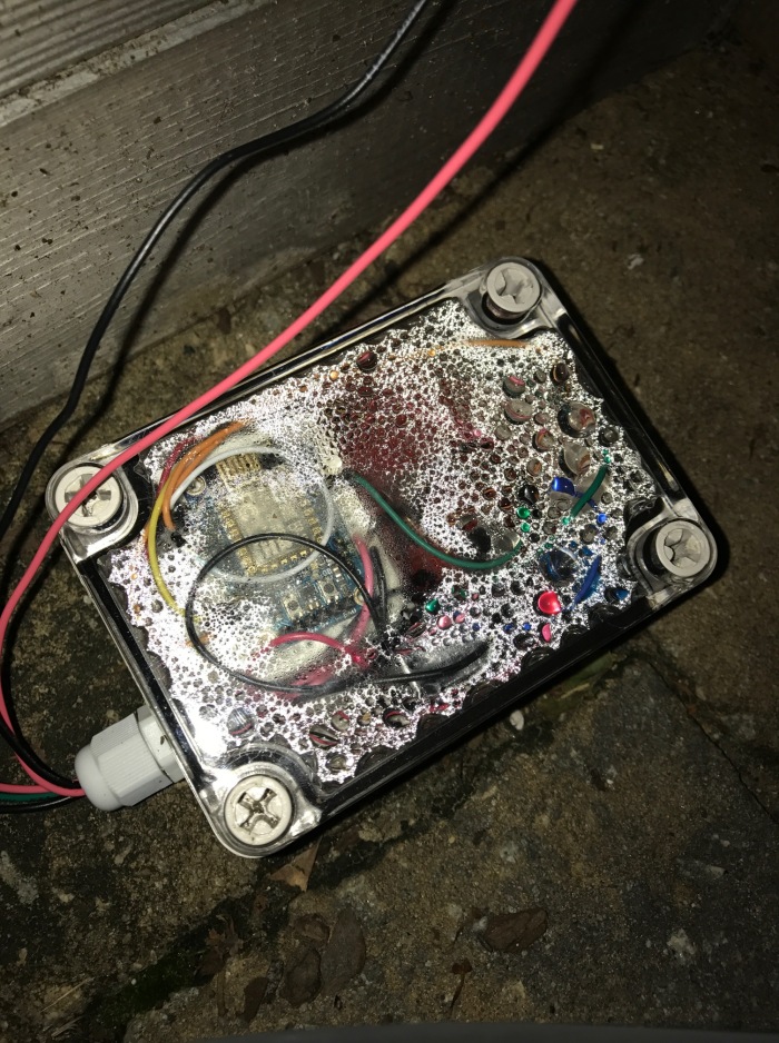
I’m not certain, but I think at least some of this had to do with the fact that the case has a clear top. The inside of the case can heat up a lot and so normal condensation and evaporation of water that happens outside could have been occurring. This is supported by the fact that the droplets were on the top of the case and the bottom only, indicating that the droplets probably formed, as opposed to leaked. The possibility of leakage through the cable gland is still there, though. The case certainly is not a problem – it was so tightly sealed that I had to pry it open. The new case doesn’t have a clear top, so hopefully that helps the problem.

So, I have to wait for my parts to arrive (should be soon). Until then, I can work on transferring my electronic parts from breadboard to stripboard, which should help clean things up and save space.

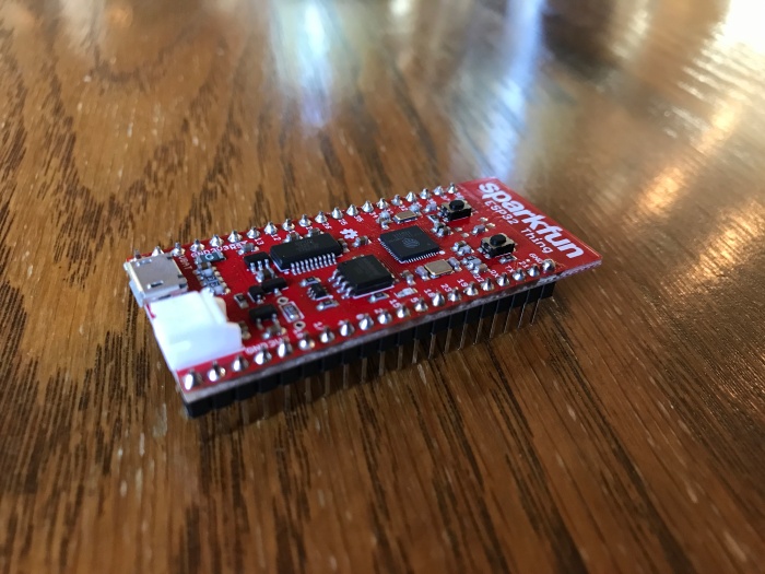
One last thing: I found out that Sparkfun is hosting a contest for ESP8266-based projects that use Cayenne, so I think I’ll be entering in that!


1. forgettability (n.) fər-ˈget-ə-ˈbi-lə-tē:

1. The ability to forget.
2. Wait, what was the word again?

2. Not that it’s a contest or anything. But if it was, I wouldn’t be cheating.

Monoprice Mini 3D Printer Unboxing and First Prints

So, I decided to jump on the increasingly large Monoprice bandwagon and get one of the amazing $200 printers.

First, I had to calibrate the bed height as instructed. The manual said that a sheet of A4 paper, which should be 0.05mm thick, would be able to slip in between the hotend nozzle and the bed when it was calibrated properly. I was planning on using a normal sheet of printer paper for this, but after breaking out the digital calipers I discovered that the printer paper I own is around .1mm thick.

This seemed like it was going to turn into some wild goose chase for .05mm thick paper, but I discovered that some college ruled paper that I had lying around would do the trick. The process of adjusting the bed height was very simple, as I only needed to rotate the screws a quarter turn before it was at the right height.

So then, it was off to printing. It works remarkably well with Cura – I had no issues, and it produced great prints.

I’m honestly surprised at the quality of the prints and the fact that nothing went horribly wrong right away. I read reviews about the printer and everyone seemed to agree that it was remarkable, but that it had some glaring issues, like a quick-to-fail power brick or a PID tuning problem with the hotend temperature. It seems like Monoprice has fixed those two problems, at least, because the power brick hasn’t failed (yet) and the hotend temperature seems to hold steady during prints.

Of course, I had to make a mistake somewhere, so I accidentally jammed the remnants of the sample white filament while trying to load some black Hatchbox filament. While fixing the problem, I got to take a closer look at the hotend – the Bowden tube is really only held on by pressure from one screw.

IMG_1684

Of all the reviews I looked at, I found Hackaday’s and John Biehler’s the most useful.

All in all, I’m satisfied with the printer, and I’m excited to start printing some cool models!

Tutorial: Using ESP-IDF to flash the ESP32 Thing

Victory! I’ve managed to upload code onto the Sparkfun ESP32 Thing using ESP-IDF. This means that (hopefully) I will be able to make full use of the chip’s capabilities, including (dare I say it?) BLE.

IMG_1337.JPG

For now, I’ll stick with “Hello world!” and LED blinking, though. The Thing has a lovely blue LED on pin 5 that is very useful for testing code and, coincidentally, Espressif provides a Blink example. Perfect!

The process of uploading the code to the ESP32 was a bit difficult for me, either because of a lack of experience or because it is actually difficult. In any case, I wanted to describe the steps I took to flash the ESP32 in case anyone else is having trouble with it.

1. Make sure ESP-IDF is set up.

Make sure that ESP-IDF is set up properly according to the steps on Espressif’s Github page. You don’t need to have Eclipse set up for this – all you need is the msys2 environment and the SDK.

2. Open msys2 and set it up.

Open up the msys2 command shell that came with the ESP-IDF installation (should be found at C:\msys32). First, we need to set the environment variable for the location of the IDF folder. Use this command:

export IDF_PATH="C:/path/to/IDF/folder/esp-idf"

There’s a way to make this run every time msys2 opens, but I haven’t figured it out yet. Next, use cd to move to the directory where your project is (not the IDF folder). For this example, I’m using Espressif’s Blink example project, with a “Hello world!” added in.

3. Configure the project.

Next, use this command:

make menuconfig

This will open a configuration screen that looks like this:

menuconfig

You can change a lot of stuff in here, but we only need to change one thing: the serial port. Navigate to Serial flasher config -> Default serial port. It will be set to /dev/ttyusb0/ or something like that – whatever it is, it doesn’t work. Delete that setting and enter the correct COM port. My ESP32 Thing showed up on COM3.

comport

Press Ok and exit the config using [ESC] [ESC].

4. Building and flashing.

Use make to build the project. The first time you do this, it will take a while. Next, plug in the ESP32 Thing and put it into bootloading mode (press button 0 and then reset, then unpress reset and then unpress button 0). Use this command to start the flashing process:

make app-flash

Do not use make flash – this tells the IDF to flash the bootloader, partition table, and application. Since we already have so much on board with the ESP32 Thing, all we need to flash is the app; this is what make app-flash does.

If everything works, this is what you’ll see:

flash.png

And just like that, we have blinking LEDs!

Since I added a “Hello world!” to the code, the ESP32 also says hello with every LED blink. To view any data that is being logged, use make monitor to create a nice serial output window.

This is a fairly unimpressive test of the ESP32, but hey, one step at a time. Next, I’ll be experimenting with connecting to wifi, hosting a wifi server, and maybe even BLE. Just maybe.

That’s all for now!

Working with the ESP32

I recently bought a Sparkfun ESP32 Thing, and I’m excited. I think the ESP8266 is really cool, so its big brother is a must have. Wifi and BLE in one chip? Awesome.

Only one problem – the Arduino library for the ESp32 doesn’t include functionality for BLE (including several other functions, like analog read and write). This was disappointing for me because without BLE, the ESP32 seems just like the ESP8266 with a few more GPIO pins. So I made a big decision: I would use Espressif’s IoT Development Framework (ESP-IDF) instead of Arduino IDE.

In short: Compared to Arduino IDE, it’s a dark and scary world out there.

I shouldn’t be too dramatic, though. Following Espressif’s setup instructions is straightforward enough and actually seems to work. Kudos to them for putting together all of this. Their Github page is also really useful. However, they use a command-line environment to build and flash the code for the ESP32. I love a good command line, but it just isn’t as familiar as an IDE.

cmd.png
We’re gonna need a bigger window.

So I tried setting up something friendlier, like Eclipse, but it doesn’t seem to work 100%. I managed to work through the difficulty of adding the various include paths, etc., but Eclipse still won’t let me flash the chip. So I’ll be using the command line until further notice – plus, I’m starting to get used to it.

I mentioned earlier that I’m using an ESP32 Thing. I think that this setup is probably a bit different from what Espressif was imagining when they designed their IDF, since the Thing has so much extra hardware that makes it easier to use. However, I think I’m getting the hang of uploading code to the ESP32 – I’ll make a tutorial for that soon, in case other people are having trouble with it.

That’s all for now!

Welcome to my blog!

Hello!

This is my blog about DIY projects that I do. I’m a maker who works on DIY projects as a hobby. I did my first projects using Arduino, but I work with other platforms too. Sometimes, I just do straight up coding – I like HTML and Javascript the best, but I’ve also worked with VB.net, C++, Python, and PHP.

I have a few projects in the works that I’ll be posting about soon, including one involving the new ESP32. Enjoy!